Roughing vs Finishing in CNC Machining
Roughing vs Finishing in CNC Machining
Roughing removes bulk material and creates the near-net shape; finishing removes a controlled final allowance to achieve the specified dimensions, geometry and machined surface. The two stages have different objectives, tools and cutting conditions. A reliable process plans them together so the roughing stage does not leave heat, distortion, chatter or uneven stock that the finishing pass cannot correct.
The terms describe machining stages, not separate manufacturing methods. Milling and turning can both include roughing, semi-finishing and finishing. The required route depends on material, part stiffness, stock condition, tolerance, surface requirement, heat treatment and production quantity.
What Is CNC Roughing? #
Roughing is the high-material-removal stage. It forms major pockets, profiles, bores, shoulders and diameters while leaving material for later passes. Productivity matters, but the process must remain stable. A roughing path that causes tool breakage, workpiece movement or severe thermal distortion does not reduce total cost.
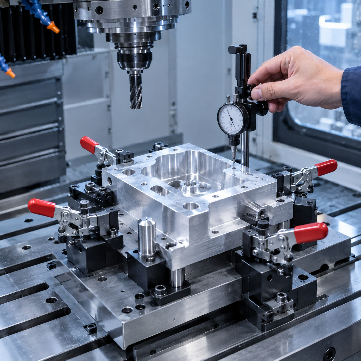
In milling, roughing may use adaptive clearing, constant-engagement paths, pocket clearing or rest machining. A robust cutter, effective chip evacuation and sufficient machine rigidity are central. Serrated roughing end mills divide chips into shorter segments, which can make evacuation easier in deep pockets. Tool choice still depends on material and geometry.
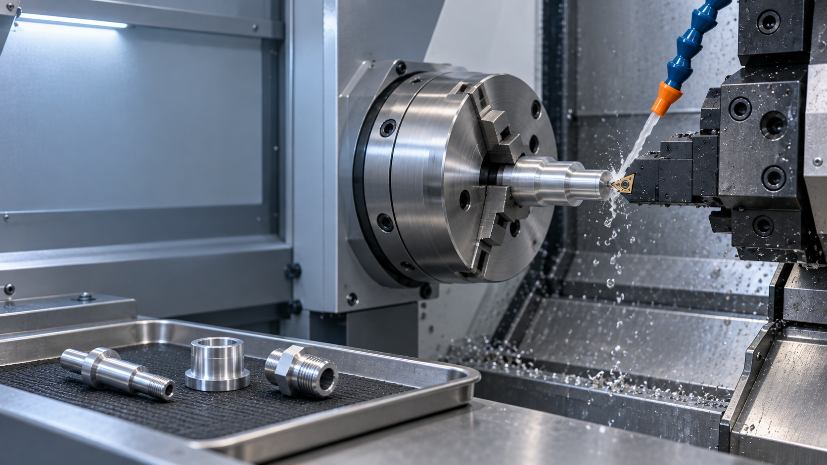
In turning, roughing reduces bar, forging or casting stock toward the final profile. The roughing insert and chip breaker must handle the selected feed, depth of cut and interrupted conditions. Long shafts and thin rings may require reduced force even when the machine has available power.
What Is CNC Finishing? #
Finishing creates final size, geometric relationships and machined surface condition. The finishing tool normally removes less material than the roughing tool, but a light cut is not automatically an accurate cut. If engagement is too small for the cutting edge, the tool may rub, generate heat or follow errors in the roughed surface.
A finish pass needs predictable stock, a sharp and suitable cutting edge, controlled runout, stable workholding and a verified offset. Critical dimensions are measured after finishing under defined conditions. Surface treatment such as anodizing, plating, polishing or bead blasting is a later process and should not be confused with CNC finish machining.
Roughing vs Finishing CNC: Key Differences #
| Process Factor | Roughing | Finishing |
|---|---|---|
| Primary objective | Remove stock efficiently | Reach final size, geometry and surface requirement |
| Remaining material | Leaves controlled allowance | Removes the final allowance |
| Cutting engagement | Generally heavier, within stable limits | Generally lighter and more consistent |
| Tool condition | Prioritizes edge strength and chip control | Prioritizes predictable edge, runout and surface generation |
| Toolpath | Stable engagement and chip evacuation | Smooth motion and consistent contact |
| Thermal effect | Can introduce substantial heat | Must account for part and machine temperature |
| Inspection | Confirms stock remains and no process damage occurred | Confirms drawing dimensions and surface requirements |
| Main failure risk | Chatter, tool overload, stock movement, uneven allowance | Size error, taper, waviness, rubbing or poor finish |
These are tendencies rather than fixed parameter rules. A flexible part may need conservative roughing. A rigid part with a broad finish face may still require enough cutter engagement to avoid rubbing.
A Practical Roughing-to-Finishing Route #
1. Review the Drawing and Stock
Identify functional datums, critical dimensions, geometric tolerances, surface-roughness callouts, thin sections and post-machining treatments. Confirm whether the blank is bar, plate, casting, forging or a pre-machined component. Stock variation influences the first roughing engagement and the allowance required for cleanup.
2. Establish Stable Datums
Machine or verify the surfaces needed to locate later operations. A final feature cannot be controlled reliably from an inconsistent raw edge. Related dimensions should remain in one setup when practical, especially when runout, position or perpendicularity is critical.
3. Remove Bulk Material
Use a path that controls tool engagement and directs cutting forces into supported areas. Maintain chip evacuation so removed chips are not cut again. Monitor spindle load, sound, vibration, chip form and tool wear during initial pieces.
4. Leave a Controlled Allowance
The roughing operation should leave continuous material on every surface that requires finishing. An uneven allowance changes cutting force during the finish pass and can push a flexible wall away from the tool. It also changes heat input and tool deflection.
There is no universal allowance that suits every component. It depends on feature size, material, roughing error, tool diameter, rigidity, heat treatment, required tolerance and the finishing process. The supplier should state the allowance used for critical features when process approval requires it.
5. Semi-Finish When Necessary
Semi-finishing creates more uniform geometry before the final pass. It is useful for deep pockets, long walls, complex surfaces, hardened parts and features where roughing leaves variable stock. It can also reveal movement after heavy material removal before the final dimensions are cut.
6. Stabilize and Inspect
Remove chips, check the fixture, inspect remaining stock and consider thermal condition. Large or heavily roughed parts may need time to approach a stable temperature. Thin or stress-sensitive parts may need unclamping, repositioning or an intermediate inspection to reveal distortion.
7. Finish Critical Features
Use a suitable tool and smooth toolpath. Control entry, exit, corner motion and tool overhang. Measure the first finished component and adjust wear offsets only after confirming that the measurement method and temperature are appropriate.
Milling: Toolpath and Tool Selection #
Efficient milling roughing aims to keep cutter engagement predictable. Sudden full-width entry, narrow internal corners and trapped chips can overload the tool. Modern constant-engagement paths can reduce engagement variation, but they still require correct feeds, speeds, stepdown, stepover and machine acceleration settings.
Rest machining removes stock that a larger rougher could not reach. It prevents a small finishing tool from unexpectedly encountering heavy corner material. For walls and pockets, separate floor and wall finishing paths may be useful because tool deflection and desired surface direction differ.
Finishing toolpaths should avoid dwell marks and abrupt direction changes on functional surfaces. Cutter runout matters because one flute can carry more load and produce a repeating pattern. Toolholder condition, projection length and spindle interface affect the result along with the cutter itself.
Turning: Rough and Finish Control #
In rough turning, insert geometry and chip breaker must suit the feed and depth of cut. Chips should break and leave the cutting zone without wrapping around the part. Unsupported workpiece length, boring-bar overhang and chuck pressure can limit the permissible load.
Finish turning uses a controlled allowance and tool-nose radius to produce final diameters and profiles. Feed per revolution influences the theoretical feed marks, but actual finish also depends on vibration, built-up edge, material, insert wear and alignment. A very small depth of cut can fail if it is below the effective cutting capability of the edge.
Bearing seats, sealing diameters and related shoulders should be planned as a group. Correcting one wear offset may change several features produced by the same tool.
Heat, Stress and Part Distortion #
Roughing changes the balance of residual stress in bar, plate, castings and forgings. Removing large volumes from one side can cause movement, particularly in thin frames and plates. Cutting heat adds temporary expansion that can hide dimensional drift.
Possible controls include balanced material removal, alternating sides, temporary ribs, additional support, an intermediate stress-relief operation where specified, and leaving enough uniform material for correction. Critical dimensions should be checked after the part is unclamped when fixture force may influence shape.
Heat treatment between roughing and finishing requires a deliberate allowance because the part may scale or distort. The process drawing and purchase order should state the heat-treatment condition in which final dimensions apply.
How Parameters Should Be Selected #
Do not copy one speed, feed or allowance table across all jobs. Parameter selection starts with the cutting-tool manufacturer's data for the exact tool, grade, diameter, material group and operation. Then adjust for radial and axial engagement, tool overhang, machine power, workholding, coolant, part stiffness and observed tool wear.
For roughing, monitor material-removal stability, chip formation, spindle load and tool life. For finishing, monitor size trend, surface texture, burr formation and edge condition. Record approved parameters and tool life for repeat orders rather than rebuilding the process from memory.
Common Defects and Corrective Actions #
| Defect | Likely Process Cause | Corrective Action |
|---|---|---|
| Finish pass leaves roughing marks | Insufficient or uneven allowance | Improve roughing accuracy or add semi-finishing |
| Chatter on finished wall | Excessive overhang, weak wall, unstable path | Support part, shorten tool, revise path and engagement |
| Dimension changes after cooling | Part finished while thermally expanded | Stabilize temperature and verify measurement timing |
| Taper on turned diameter | Workpiece or tool deflection | Improve support and reduce finishing force |
| Dwell mark on surface | Tool stopped or changed direction under contact | Use continuous motion and controlled lead-in/lead-out |
| Burr increases after finishing | Worn edge or unsuitable exit direction | Replace tool and revise exit or deburring plan |
| Finish tool breaks in corner | Unremoved rest material | Add rest roughing or semi-finishing |
Design and Purchasing Guidance #
Apply tight tolerances and surface callouts only to functional features. A requirement applied to every surface can force unnecessary finishing paths and inspection. State datum relationships clearly so the supplier can keep related features in the same setup.
For machining materials, specify the exact grade and condition. Material condition changes tool selection, cutting response and possible distortion. Identify surfaces affected by coating or plating and state whether final dimensions apply before or after treatment.
When reviewing CNC machining capabilities, ask the supplier to explain:
- the roughing, semi-finishing and finishing sequence;
- how finishing allowance is controlled on critical features;
- whether roughing and finishing use separate tools;
- how heat and fixture distortion are managed;
- which dimensions are checked during the first article;
- how tool wear is monitored during the batch;
- how revised drawings change the established process.
What to Send for Quotation #
Provide a STEP model and controlled PDF drawing, material grade and condition, quantity, critical tolerances, surface requirements, heat treatment, coating, inspection documents and delivery location. Mark sealing faces, bearing fits and datum features. If an existing process has failed, provide measurement data and photographs instead of asking only for “better finishing.”
Send these files to request a manufacturing review for custom CNC machined parts. The supplier can then plan roughing and finishing around the actual functional requirements.
Roughing vs Finishing CNC FAQ #
Can one tool perform both roughing and finishing?
Yes, for some simple, rigid parts and short runs. Separate tools are often useful when roughing wear would make final size or surface condition less predictable.
Is finishing always a very light cut?
No. The cut must be small enough for control but large enough for the edge to cut cleanly. Tool geometry, material and machine stability determine the workable range.
Why is semi-finishing required?
It creates a uniform allowance, removes roughing errors and reveals distortion before the final pass. Complex surfaces, deep pockets and tight-tolerance features benefit most.
How much stock should roughing leave?
There is no universal value. Base it on feature size, roughing variation, material, rigidity, heat treatment, finish tool and final tolerance.
Does finishing remove all roughing distortion?
Not necessarily. Finishing can correct remaining geometry only within its allowance and part stability. Stress movement or clamp distortion may remain after release.
Is machined surface finish the same as anodizing or polishing?
No. Finish machining creates geometry and tool-generated texture. Anodizing, polishing, plating and blasting are separate downstream processes.
What should be inspected between roughing and finishing?
Check remaining stock, datum condition, fixture seating, tool damage and major distortion. For critical work, verify representative dimensions before committing to the final pass.
Conclusion #
Roughing and finishing should be designed as one process. Roughing must remove stock without damaging the part or leaving an unpredictable allowance. Finishing must use stable tools, temperature, workholding and inspection to convert that allowance into the drawing requirements. Buyers should evaluate the complete route rather than judging a supplier from a single quoted tolerance or surface value.
CNC Turning: How the Process Works, Common Operations, and Design Tips
CNC Turning Process: From Raw Bar to Finished Part
Related Article