CNC Turning: How the Process Works, Common Operations, and Design Tips
CNC Turning Guide
CNC Turning: How the Process Works, Common Operations, and Design Tips
CNC turning is a machining process in which a workpiece rotates while a cutting tool removes material to create cylindrical features. It is commonly used for shafts, pins, bushings, spacers, threaded components, and other parts with round geometry. A successful CNC turning project starts with a clear drawing, suitable workholding, accessible tool paths, and defined inspection requirements.
What Is CNC Turning?
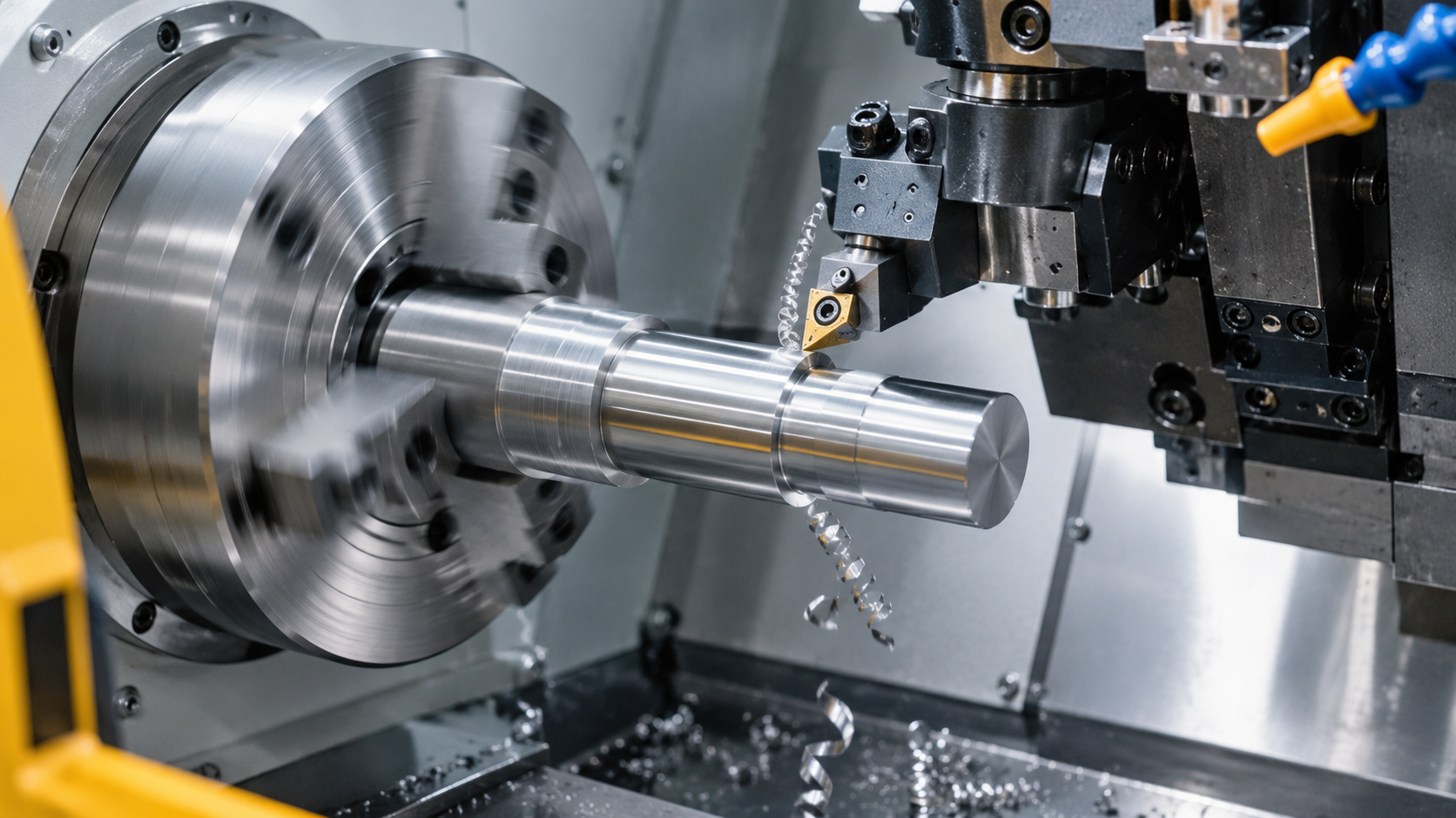
In CNC turning, the machine holds and rotates the workpiece around its spindle axis. A cutting tool moves along programmed paths and removes material from the outside diameter, face, or interior of the part. The CNC program coordinates spindle rotation, tool movement, feed, and other process settings.
Unlike CNC milling, where a rotating cutter commonly moves around a stationary or repositioned workpiece, conventional turning makes the workpiece itself rotate. This makes turning a natural option for parts whose important features are concentric or rotationally symmetric. A turned part can still include flats, cross-holes, pockets, or other non-round features, but those may require live tooling, a secondary milling setup, or another process. Confirm the available machine configuration with the supplier.
How Does the CNC Turning Process Work?
- Review the part definition. The machinist checks the 2D drawing and 3D model for material, stock size, datum scheme, diameters, lengths, shoulders, grooves, threads, tolerances, and surface requirements.
- Choose stock and workholding. Bar stock or a cut blank is held in an appropriate chuck, collet, or other workholding arrangement. The setup must support the part without compromising access to critical surfaces.
- Plan tools and tool paths. Turning tools, boring tools, drills, grooving tools, or threading tools are selected for the geometry and material. The sequence is programmed to remove material while maintaining tool access and control of chips.
- Machine and manage the process. The spindle rotates the workpiece as the cutting tool follows its programmed path. The operator or automated process checks the setup, cutting behavior, tool condition, and chip evacuation.
- Finish and inspect. Critical dimensions and surfaces are checked against the drawing. If the part needs features that cannot be made in the turning setup, a secondary operation may follow.
The actual sequence depends on the part, machine, tooling, stock, and production quantity. There is no single cycle or tolerance that applies to every CNC-turned component.
Common CNC Turning Operations
External turning
External turning reduces or profiles the outside diameter of a workpiece. It can create straight cylindrical sections, tapers, shoulders, and contours. Call out the diameters and their relationship to functional datums, especially where the part fits a bearing, seal, housing, or mating component.
Facing
Facing machines the end of the workpiece to create a flat end surface and establish or refine part length. If the end face is a locating surface, identify it as a datum and specify the relevant flatness or perpendicularity requirement only when function requires it.
Boring and internal turning
Boring enlarges or finishes an existing hole from inside the part. Deep or narrow bores can be sensitive to tool reach, chip evacuation, and vibration. Provide bore depth, diameter, entry details, and any required concentricity or surface condition so the supplier can assess the setup.
Grooving and parting off
Grooving creates a narrow recess on an external or internal surface. Parting off separates a finished component from bar stock. Groove width, depth, corner geometry, and nearby shoulders can affect tool access and the machining sequence.
Thread turning
Thread turning forms external or internal threads with a threading tool following a controlled path. Specify the thread standard, nominal size, pitch, class or tolerance, usable length, thread relief, and any inspection gauge requirements. Do not rely on a model alone to communicate a thread specification.
Drilling and live-tool features
A lathe may drill along the spindle axis, and some turning centers can machine off-axis features with live tooling or additional axes. These options are machine-dependent. For cross-holes, flats, slots, or bolt patterns, ask whether they can be completed in one setup or require secondary milling.
What Parts Are Well Suited to CNC Turning?
Turning is especially suitable when a component is primarily round and its key features share a common axis. Typical examples include:
- Shafts, pins, rollers, and spacers
- Bushings, sleeves, and cylindrical inserts
- Threaded studs, adapters, and fittings
- Round housings, collars, and bearing seats
- Precision prototypes and production components with rotational geometry
A part with extensive prismatic geometry may be more efficiently milled, while a hybrid design may need both turning and milling. The best route depends on its geometry, quantity, material, critical tolerances, and how the part will be inspected.
Design Tips for CNC-Turned Parts
- Make the rotational datum clear. Identify the axis or datum structure that controls concentric features and mating diameters.
- Keep critical features accessible. Deep shoulders, narrow grooves, long bores, and tight internal corners can limit tool access. Ask for a manufacturability review when these features are essential.
- Specify threads completely. Include the standard, size, pitch, tolerance class, thread length, and any relief or gauge requirement.
- Apply tight tolerances selectively. Tighten only dimensions tied to fit, sealing, alignment, or function. Unnecessarily tight tolerances can add machining and inspection effort.
- Consider stock and part length. Long, slender parts may need additional support or a different process plan to manage deflection and vibration. Ask the supplier to review the actual geometry.
- Plan edge conditions and finish. State whether edges need a break, chamfer, deburring, or a defined surface finish. Clarify which surfaces are functional.
- Provide consistent files. Submit a revision-controlled 2D drawing and 3D model. Use the drawing to communicate dimensions, tolerances, material, threads, and inspection requirements.
What Affects CNC Turning Quality?
Dimensional consistency and surface quality depend on the interaction of the machine, workholding, tool condition, material, programming, and inspection method. A secure setup helps limit movement; suitable tool geometry and cutting conditions help control chip formation and finish; and a clear datum scheme lets the supplier measure the features that matter.
For internal turning, long tool overhang can increase vibration risk. The appropriate response depends on bore geometry, tool reach, material, workholding, and the available process. Workholding options such as chucks and collets must be selected for the specific part and setup; they are not interchangeable assumptions.
When a feature is critical, define how it relates to other features and what evidence is required. If you need a first-article report, material documentation, or a specific inspection record, state that in the RFQ and have the supplier confirm availability before placing the order.
CNC Turning vs. CNC Milling
Choose turning when the part is mainly cylindrical and its important diameters, faces, grooves, or threads can be machined efficiently around a spindle axis. Choose milling when the dominant geometry consists of flat faces, pockets, slots, or features distributed across multiple sides. Some CNC turning centers include live tooling, and some parts combine turning and milling; these capabilities vary by machine and supplier.
When a part combines round and prismatic features, compare the setup count, datum strategy, tool access, and inspection plan for each process route.
CNC Turning RFQ Checklist
To help a supplier review and quote a turned part, include:
- Revision-controlled 2D drawing and 3D model
- Material grade and condition, plus any allowed alternatives
- Stock form or bar requirements, if important to the design
- Critical diameters, lengths, datum references, tolerances, and surface requirements
- Complete thread specifications and inspection-gauge requirements
- Quantity, prototype or repeat-production intent, and requested delivery window
- Required inspection documents, material certificates, finish, packaging, and destination
Ask the supplier to flag features that may need a secondary milling operation, special workholding, or a change to the design. Confirm any process limits, tolerances, and inspection deliverables against the specific part rather than assuming a standard capability.
Frequently Asked Questions
Does CNC turning only make simple round parts?
No. Turning is centered on rotational geometry, but turning centers with suitable live tooling or additional axes may also produce some off-axis features. The available operations depend on the machine configuration and setup.
Can CNC turning make internal features?
Yes. Drilling and boring can create or finish internal features. Bore depth, diameter, tool reach, and chip evacuation affect the process plan.
Is CNC turning more accurate than milling?
Neither process is universally more accurate. Achievable results depend on the part, machine, workholding, material, tool, process control, and inspection plan. Put functional tolerances on the drawing and confirm them with the supplier.
Can a turned part include cross-holes or flats?
Sometimes. A turning center with compatible live tooling or additional axes may complete them; otherwise, a secondary milling setup may be needed. Confirm this during design review and quotation.
CNC Workholding & Fixture Design: The Key to Consistent CNC Parts
Roughing vs Finishing in CNC Machining
Related Article