CNC Turning Process: From Raw Bar to Finished Part
CNC Turning Process: From Raw Bar to Finished Part
CNC turning is a subtractive manufacturing process in which a workpiece rotates while a cutting tool removes material from its outside or inside diameter. It is normally the first process to consider for shafts, pins, bushings, sleeves, threaded connectors, rollers and other parts whose main features share a central axis. A reliable turning plan connects drawing review, workholding, tooling, roughing, finishing, deburring and inspection into one controlled sequence.
What Is CNC Turning? #
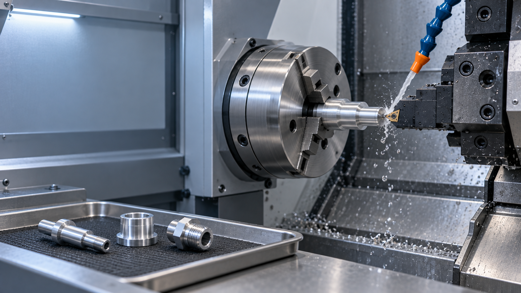
A CNC lathe holds round stock in a chuck or collet and rotates it on the spindle. Cutting tools mounted on a turret move primarily along the X axis, which controls diameter, and the Z axis, which controls length. The tool follows programmed coordinates to create faces, steps, tapers, grooves, bores and threads.
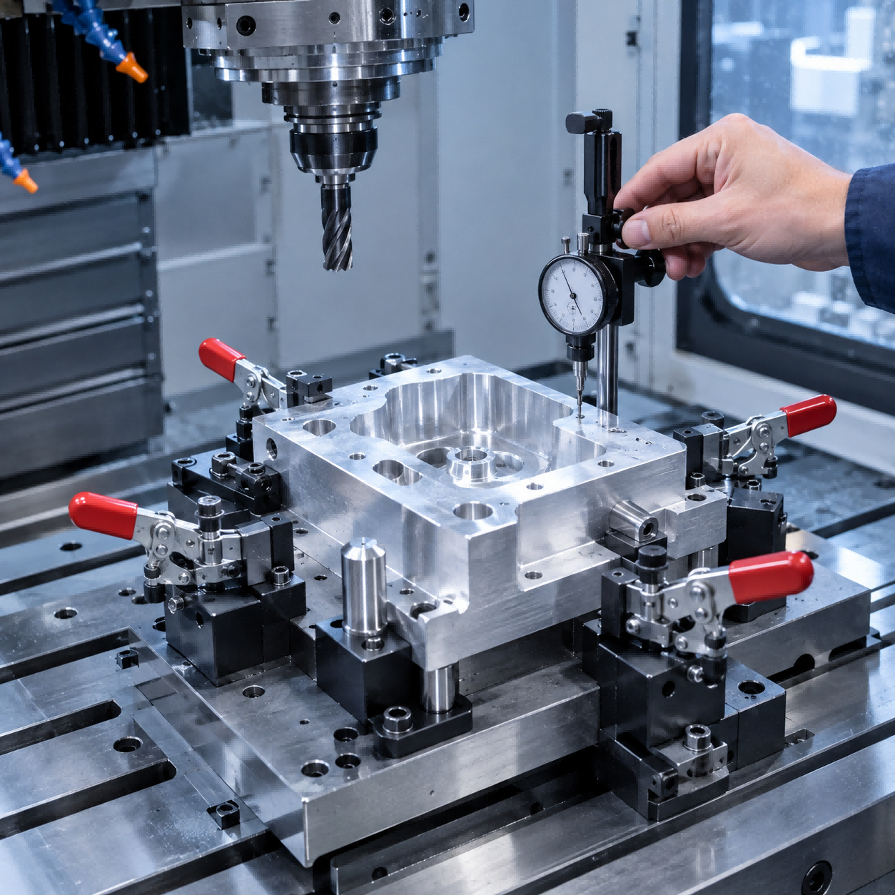
This motion distinguishes turning from milling. In turning, the workpiece rotates and a single-point tool usually performs the cut. In milling, the cutter rotates around a stationary or indexed workpiece. Turning is generally efficient when most of the geometry is rotationally symmetric. Milling is usually more suitable for prismatic parts with broad flat faces, pockets and features distributed across several sides.
Turning centers may add live tooling, controlled rotary axes or a sub-spindle for cross-holes, flats and second-side work. Confirm the machine configuration during quotation because it affects access, setup count and price.
Which Parts Are Suitable for CNC Turning? #
The best turning candidates have a clear axis of rotation. Common examples include:
- shafts with several outside diameters;
- bushings with controlled inside and outside diameters;
- pins, spacers and sleeves;
- hydraulic or pneumatic fittings;
- threaded connectors and fasteners;
- valve components;
- rollers and bearing seats;
- round housings and caps.
A part can include flats, radial holes and slots when live tooling or secondary milling is available. Turning becomes inefficient when rectangular geometry, large off-axis pockets or multi-directional access dominate the design.
The Complete CNC Turning Process #
1. Review the CAD Model and Drawing
Review the latest 3D model and controlled 2D drawing for dimensions, datums, tolerances, threads, finish requirements, tool access and secondary operations.
Important questions include:
- Which diameter establishes the primary datum?
- Which features require concentricity or runout control?
- Are internal grooves or deep bores accessible?
- Does the drawing distinguish critical dimensions from reference dimensions?
- Are thread standards, classes and inspection requirements complete?
- Are sharp edges functionally necessary?
Resolving these points before programming prevents different interpretations during machining and inspection.
2. Select the Raw Material
Round bar, tube, forgings and pre-machined blanks may be used. Stock must cover the finished envelope and cleanup allowance. Tube reduces removal on hollow parts, but its bore, wall variation and straightness must suit the design.
Aluminum, stainless steel, alloy steel, brass, copper, titanium and engineering plastics respond differently to force and heat. State the exact grade and condition in the quotation, and request any material certificate before stock is purchased.
3. Plan Workholding and Datums
Three-jaw chucks, collets and soft jaws must transmit torque without crushing or marking the part. Collets suit repeatable bar work; machined soft jaws support larger diameters and protect finished surfaces.
Long, slender parts may need a tailstock, live center, steady rest or follow rest. Unsupported length increases the risk of bending, taper and chatter. Thin-wall rings and tubes need controlled clamping force because jaw pressure can distort the part before cutting begins.
If the second end must be machined, the part may be reversed into soft jaws or transferred to a sub-spindle. Features with tight relationships should remain in one setup whenever practical.
4. Program the Toolpath
CAM software or manual programming defines tool positions, spindle direction, speed, feed, depth of cut, coolant and safe approach positions. A typical program covers facing, rough turning, drilling or boring, grooving, threading, finishing and parting. Tool-nose-radius compensation accounts for the insert radius around profiles and tapers. Simulation checks clearance, while the first machine cycle confirms offsets and the physical setup.
5. Set Up Tools and Establish Offsets
Each tool is loaded into a known turret station. X and Z offsets define the insert tip relative to the work coordinate system, while wear offsets support controlled corrections. Insert shape, grade, chip breaker and nose radius must match the material and operation. Boring bars need adequate rigidity, and threading inserts must match the specified form and pitch.
6. Face and Rough-Turn the Part
Facing creates a controlled end surface and establishes the Z datum. Rough turning then removes most of the excess material from the outside diameter. The objective is stable material removal while leaving a consistent allowance for finishing.
Roughing depends on material, insert, power, rigidity and chip evacuation. Excessive engagement can overload the insert or deflect the part; an overly light cut can rub instead of cutting. Chips must break and evacuate without wrapping around the tool or workpiece.
7. Drill, Bore, Groove and Thread
Axial holes may begin with a center drill or spot drill followed by drilling. Boring improves hole size, straightness and concentricity relative to the turned outside diameter. Deep bores require particular attention to bar overhang, coolant delivery, chip evacuation and measurement access.
Grooving tools create reliefs, seal grooves and retaining-ring features. Narrow or deep grooves increase tool deflection and make chip removal more difficult. Threads may be cut with a single-point insert, tap or die depending on thread location, size, tolerance and quantity. A complete thread specification should include the standard, nominal size, pitch or threads per inch, class or tolerance, handedness and required length.
8. Finish Critical Features
Finishing passes bring diameters, shoulders and profiles to final size and surface condition. A stable finish depends on consistent stock allowance, a suitable insert nose radius, limited tool wear and controlled heat.
The operator may measure a trial part and adjust wear offsets before continuing the batch. Dimensions should not be corrected in isolation: changing one tool offset can affect several features produced by that tool. Critical relationships such as bearing-seat diameter, shoulder location and runout should be reviewed together.
9. Part Off and Machine the Second Side
A parting tool separates the component from bar stock. The cutoff face may require a second operation to achieve final length, surface finish or chamfer. During reversal, the operator must protect finished diameters from jaw marks and control axial seating against the locating face.
Sub-spindle transfer can reduce handling, but its availability must be confirmed for the project.
10. Deburr, Clean and Inspect
Turning can leave burrs at cross-holes, grooves, threads and cutoff edges. Deburring removes loose material and breaks edges according to the drawing. Functional sharp edges should be identified rather than assumed.
After cleaning, inspection confirms the drawing. Typical tools include micrometers for outside diameters, bore gauges for internal diameters, thread gauges, indicators and—where appropriate—a coordinate measuring machine.
Common CNC Turning Operations #
| Operation | Purpose | Main Control Point |
|---|---|---|
| Facing | Produces a flat end and establishes length datum | Flatness and Z position |
| OD turning | Reduces and profiles outside diameters | Diameter, taper and surface finish |
| Boring | Enlarges and finishes an internal diameter | Size, straightness and bar deflection |
| Grooving | Produces relief or retaining features | Width, depth and corner form |
| Threading | Produces internal or external threads | Pitch, form, class and effective length |
| Parting | Separates the component from stock | Burr, cutoff stability and final allowance |
| Live-tool machining | Adds flats, slots and radial holes | Angular position and feature-to-datum relationship |
Design Guidelines for Turned Parts #
Control Long, Slender Geometry
A high length-to-diameter ratio reduces stiffness. Cutting force can bend the part away from the tool, producing taper, chatter or inconsistent diameter. Increase diameter, shorten unsupported length, allow center support or divide machining into controlled stages when the function permits.
Avoid Unnecessarily Thin Walls
Thin tubes and rings can deform under chuck pressure and tool load. They may appear within tolerance while clamped but change shape after release. A thicker wall, temporary support, lower cutting pressure or a dedicated fixture can improve stability. Minimum wall thickness is not a universal number; it depends on diameter, material, length, tolerance and holding method.
Provide Tool Access to Internal Features
Deep internal grooves, small bores and internal threads need room for a toolholder and chip evacuation. The bore diameter must accept a sufficiently rigid boring bar. Where possible, increase access diameter, reduce depth or move the feature closer to the opening.
Specify Practical Corner Conditions
Turning tools have a nose radius, so perfectly sharp internal corners are not produced by a standard profile pass. Define an acceptable radius, undercut or relief where mating components require clearance. Outside edges should use a stated chamfer or radius instead of an undefined “break edge” when the edge affects assembly.
Dimension from Functional Datums
Place size and location tolerances in relation to the surfaces that control assembly. Use runout, concentricity or position only where the function requires them, and define a datum structure that can be reproduced during manufacturing and inspection. Excessive decimal places without functional tolerance do not improve the part.
How Turning Accuracy Is Controlled #
Accuracy depends on workholding repeatability, tool overhang, insert wear, material variation, heat, program strategy and measurement—not the machine specification alone.
Useful controls include:
- producing related diameters in one setup;
- minimizing tool and workpiece overhang;
- using stable finishing allowance;
- separating roughing heat from final measurement;
- monitoring tool wear and using controlled offset corrections;
- defining inspection temperature and method for critical dimensions;
- verifying the first article before releasing the batch.
A tolerance should always be discussed with its feature size, material, geometry, surface finish and inspection method. A single tolerance claim for every turned feature is not technically meaningful.
Common Turning Defects and Corrective Actions #
| Defect | Likely Causes | Process Response |
|---|---|---|
| Chatter marks | Low rigidity, excessive overhang, unstable parameters | Support the part, shorten overhang, adjust speed/feed, change tool geometry |
| Tapered diameter | Part deflection, alignment issue, heat | Improve support, reduce cutting force, check alignment and thermal condition |
| Poor surface finish | Worn insert, built-up edge, vibration, unsuitable feed | Replace insert, improve stability, revise cutting conditions |
| Oversize or undersize bore | Boring-bar deflection, tool wear, incorrect offset | Use a more rigid bar, control allowance, correct wear offset |
| Thread gauge failure | Wrong insert/pitch, offset error, burrs | Verify specification and tool, inspect pitch diameter, remove thread burrs |
| Jaw marks or distortion | Excessive clamping force or poor contact | Use soft jaws/collet, increase support area, reduce clamping pressure |
What to Send for a CNC Turning Quote #
Provide both a 3D model and a controlled 2D drawing when possible. The RFQ package should include:
- material grade and condition;
- required quantity and expected repeat orders;
- critical dimensions and tolerances;
- datum and geometric-control requirements;
- thread standards and gauge requirements;
- surface roughness where functionally necessary;
- deburring and edge requirements;
- surface treatment and masking requirements;
- material certificates or inspection reports required;
- target delivery date and shipping destination.
Clear inputs allow the supplier to choose the process, machine configuration, tooling, workholding and inspection plan before quoting.
CNC Turning Process FAQ #
What is the difference between CNC turning and CNC milling?
In CNC turning, the workpiece rotates while a cutting tool moves along the part, making the process efficient for cylindrical geometry. In CNC milling, the cutting tool rotates and moves around a stationary or indexed workpiece, making it better suited to prismatic parts, pockets and multiple faces.
Can a CNC lathe produce flats and cross-holes?
Yes, when the turning center has suitable live tooling and controlled spindle positioning. Otherwise, flats, slots and cross-holes require a separate milling or drilling setup. Include these features in the 3D model and drawing so the supplier can select the correct route.
How are tight diameter tolerances maintained?
Manufacturers control workholding, tool overhang, finishing allowance, insert wear, heat and measurement. Trial parts are measured, and controlled wear-offset corrections may be applied. The achievable tolerance depends on diameter, material, geometry, batch conditions and inspection method.
Why do long shafts develop taper or chatter?
Long shafts have lower bending stiffness. Cutting force can push the material away from the tool, while vibration can produce repeating surface marks. A tailstock, steady rest, reduced overhang, suitable tool geometry and revised cutting parameters can improve stability.
Should threads be modeled in the 3D file?
The model may show the thread envelope, but the drawing must state the standard, size, pitch, class, handedness, effective length and gauge requirement.
What inspection documents can be requested?
Buyers may request a dimensional report, first article report, material certificate or certificate of conformity. State the document and sampling requirement in the RFQ.
What files are useful for quotation?
Send a neutral 3D model and controlled drawing showing revision, material, tolerances, threads, finish and inspection requirements. Confirm the supplier's accepted formats first.
Request a Manufacturing Review #
Send your drawing, material, quantity and critical requirements to request a manufacturing review and quotation. OPICREATE can review whether the part is better suited to CNC turning, CNC milling or a combined process before production planning.
Roughing vs Finishing in CNC Machining
CNC Milling Explained: 3-Axis, 4-Axis, and 5-Axis Machining Guide
Related Article