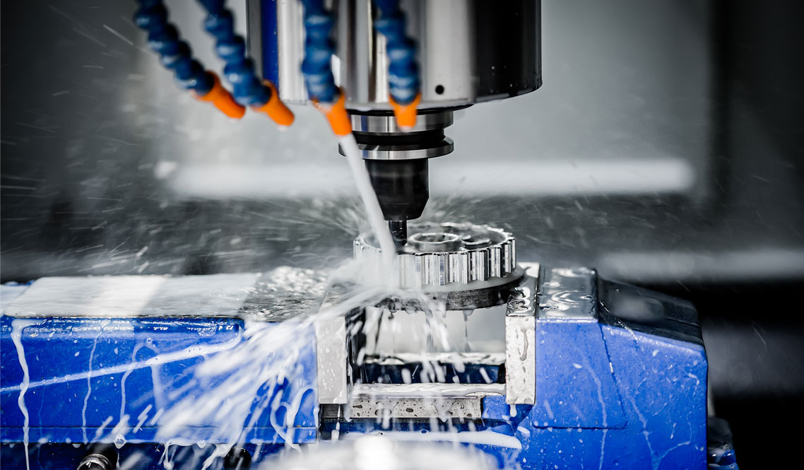
CAM Programming for CNC Machining: How Toolpaths Are Created
CAM Programming for CNC Machining: How Toolpaths Are Created
Learn how CAM software converts 3D models into machine-ready G-code. Understand toolpath strategies for roughing, finishing, and multi-axis machining.
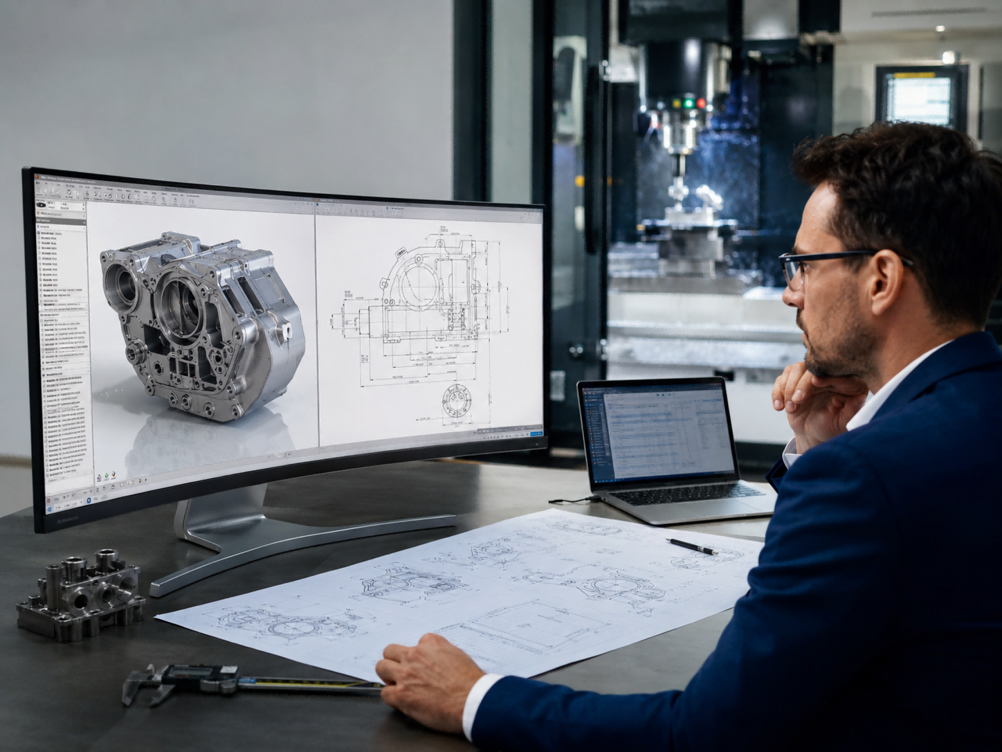
Get Expert CNC Programming SupportCAM (Computer-Aided Manufacturing) is the bridge between your 3D model and the physical part. Without proper cnc programming, even the best design cannot be machined efficiently. In this guide, we explain how our programmers create toolpaths and generate the g code programming that drives our CNC machines.
Whether you need simple 3-axis milling or complex 5-axis machining, understanding the CAM process helps you communicate better with your manufacturing partner.
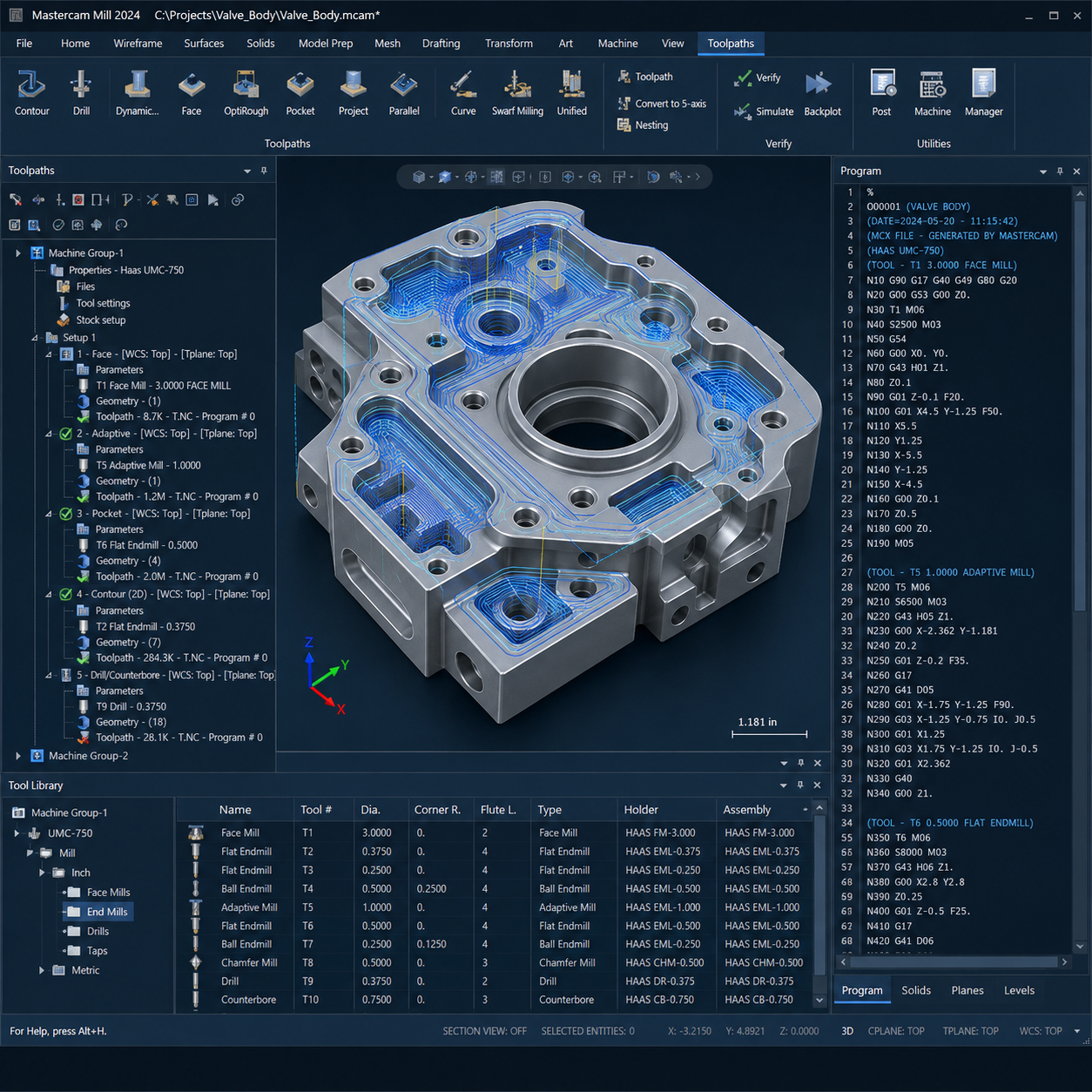
The CAM Process Step by Step
Here is how we turn your 3D model into a machinable program:
- Import the 3D Model – We load your STEP or IGES file into CAM software.
- Define the Stock – We specify the raw material block size.
- Select Cutting Tools – We choose end mills, drills, taps, and other tools based on geometry and material.
- Set Cutting Parameters – Speeds, feeds, and depth of cut are optimized for the material and tool.
- Generate Toolpaths – The software creates the path for each operation.
- Simulate – We run a virtual simulation to detect collisions or errors before machining.
- Post-Process – The toolpaths are converted into G-code specific to our CNC machines.
Common Toolpath Strategies
Different features require different approaches. Here are the most common toolpath strategies we use:
- Facing – Flattens the top surface of the stock
- Roughing – Removes bulk material quickly with larger tools
- Finishing – Achieves final dimensions and surface quality
- Drilling – Creates holes with precise diameters and depths
- Thread milling – Cuts internal or external threads
- Contouring – Follows complex curves and profiles
Each strategy has specific parameters for cutting speed, feed rate, and stepover. Our programmers select the best combination for your part's geometry and tolerance requirements.
3-Axis vs 4-Axis vs 5-Axis Toolpaths
The number of axes affects the complexity of toolpaths and the types of parts you can machine:
| Machining Type | Tool Movement | Best For |
|---|---|---|
| 3-Axis | Moves in X, Y, Z | Simple parts with flat features |
| 4-Axis | Adds rotation around one axis (A) | Multi-sided parts, cylindrical features |
| 5-Axis | Adds rotation around two axes | Complex geometries, undercuts, deep cavities |
Using 4-axis or 5-axis machining can significantly improve accuracy and reduce lead time for complex parts. Our CAM programmers are experienced in generating efficient toolpaths for all three types.
Need Expert CNC Programming for Your Parts?
Our CAM programmers are ready to turn your design into a precise machining program. Get a fast quote and free DFM feedback.
CNC Milling Explained: 3-Axis, 4-Axis, and 5-Axis Machining Guide
CNC Metal Material Selection Guide: Aluminum, Stainless Steel, Titanium & More
Related Article